The cost of getting this wrong is high: premature capacity fade, thermal hot spots, short circuits from cell-to-busbar contact, and in worst cases, thermal runaway propagation across a module.
This article covers battery cell holders and battery trays together — what each component is, how they differ structurally, the materials used in modern designs, and the engineering best practices that separate production-ready designs from problematic ones. The guidance applies across EV, automotive, drone, railway, and industrial battery systems.
You'll leave with a working understanding of material trade-offs, design constraints by cell format, and the manufacturing and compliance considerations that matter in practice.
Key Takeaways
- Cell holders vs. trays: Holders position and retain individual cells within a module; trays are the structural lower enclosure housing the full pack
- Material selection depends on thermal performance, flammability requirements, mechanical loads, and weight targets; engineering polymers dominate holders, aluminium alloys dominate trays
- Cell format drives geometry: cylindrical, prismatic, and pouch cells each impose fundamentally different holder requirements
- Non-negotiable requirements include UL94 V-0 flammability rating, IP sealing, vibration resistance, and thermal runaway containment
- Precision injection moulding is the dominant manufacturing method for polymer cell holders at production scale
Battery Cell Holders vs. Battery Trays: Understanding the Key Difference
In procurement conversations, battery cell holders and battery trays are often treated as synonyms. They aren't — each serves a distinct engineering function, and conflating them leads to misaligned specifications.
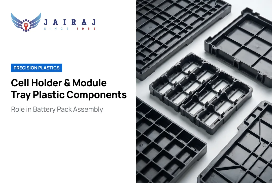
What a Cell Holder Is
A battery cell holder is a sub-component — typically a polymer or composite frame — that positions, isolates, and retains individual battery cells within a module. Its job is precision: keeping each cell exactly where it belongs, electrically isolated from adjacent cells, and in consistent thermal contact with the cooling interface.
Holders prioritise:
- Dimensional precision and pocket-bore consistency
- Electrical isolation between cells and from metallic structures
- Thermal pathway to the cooling plate
- Retention under vibration and shock loading
What a Battery Tray Is
A battery tray is the structural lower enclosure of the complete pack. It carries the combined weight of all modules, interfaces with the vehicle or equipment chassis, and houses both high- and low-voltage components. Where a cell holder manages individual cell positioning, the tray manages pack-level structural integrity — a fundamentally different engineering challenge.
Trays prioritise:
- Load-bearing structural integrity under crash and operational loads
- IP sealing (dust and water ingress protection)
- Thermal management integration (cooling plate mounting, coolant routing)
- Crash protection and intrusion resistance
- Serviceability and module-level access for maintenance
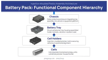
The Functional Hierarchy
Understanding these two components separately makes the overall pack architecture easier to reason about. The hierarchy is straightforward:
Cells sit in holders → holders or cell assemblies sit in the tray → the tray mounts to the vehicle or system chassis.
In Cell-to-Pack (CTP) architectures — such as BYD's Blade Battery or CATL's Qilin platform (which achieves 72% volume utilisation) — discrete cell holders may be replaced by structural adhesive bonding directly into the tray. But the tray itself remains a distinct engineering component regardless of architecture.
Types of Battery Cell Holders: Designing for Cylindrical, Prismatic, and Pouch Cells
Cell format drives every downstream holder decision — geometry, retention method, material selection, and thermal strategy all follow from it. Getting this choice right at the outset prevents costly redesigns later.
Cylindrical Cell Holders (18650, 21700, 4680)
Cylindrical cells require individual pockets or sleeves that constrain lateral movement while accommodating axial expansion during charge/discharge cycling. Holders are typically injection-moulded polymer grids or end-plates with precision-bored pockets arranged in rows or hexagonal arrays.
Two variables dominate cylindrical holder design:
- Pocket bore tolerance: Oversized pockets cause cell rattle and degrade thermal contact with the cooling plate; undersized pockets stress the cell casing during insertion. Per ISO 20457, tolerances must be specified against actual moulding process parameters — resin shrinkage, tool class, and part size — not a universal figure.
- Cell spacing: Gaps between cells must accommodate airflow in air-cooled designs or allow cooling plates to snake between rows in liquid-cooled systems. This spacing also acts as a thermal and electrical buffer between adjacent cells.
Prismatic Cell Holders
Prismatic cells — flat, rigid aluminium or steel cans — are typically arranged vertically in a row. Holders or end-frames apply controlled compression through compression pads or foam to prevent module swelling from delaminating cells over cycling.
In CTP designs, prismatic cells are bonded directly into the tray using structural adhesive with integrated thermal interface materials. This approach, used in BYD's Blade Battery, improves space utilisation by over 50% versus conventional module-based packs — but requires very precise tray floor flatness and eliminates the discrete holder entirely.
Pouch Cell Holders
Pouch cells present the most complex holding challenge. Their flexible foil casing provides no inherent rigidity, which means:
- The holder must supply a rigid supporting frame to prevent deformation and vibration fatigue
- Tab connectors are vulnerable to stress from cyclic swelling — the holder must manage this mechanically
- The conductive foil pouch must be electrically isolated from adjacent cells and from the metal tray
- Research on pouch cell compression recommends flexible compression of 0.2 MPa to 0.5 MPa as the design target for balancing capacity fade, internal resistance, and irreversible swelling
Pouch holders often incorporate compliant compression features — foam inserts or spring-loaded plates — that maintain contact pressure while accommodating thickness changes during cycling.
Material Selection for Battery Cell Holders and Trays
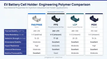
Engineering Polymers for Cell Holders
Polymer selection starts with one non-negotiable: UL94 V-0 flammability rating (or IEC 60695-11-10 equivalent). Any material in close proximity to battery cells must meet this baseline before other properties are evaluated.
Common material options for EV-grade cell holders:
| Polymer | Key Strengths | Notes |
|---|---|---|
| PA66-GF30 | High strength, excellent heat resistance | BASF Ultramid A3EG6: HDT of 250°C at 1.8 MPa (ISO 75); CTE ~28 × 10⁻⁶/K longitudinal |
| PA66-GF FR | V-0 compliance + structural performance | BASF Ultramid A3U42G6: UL94 V-0 at 0.4 mm thickness |
| PP-GF30 FR | Cost-effective, good chemical resistance | LyondellBasell Polyflam RPP 4230: UL94 V-0 at 1.5 mm; RTI 65°C |
| PC | High impact resistance, dimensional stability | Strong for electrical isolation applications |
| POM | Excellent precision, low friction | Preferred for sliding retention features |
Glass fibre reinforcement — typically 15–30% by weight — is standard for EV-grade holders. Key advantages of GF reinforcement:
- Increases stiffness for tighter cell retention
- Reduces creep under sustained compressive loads
- Maintains dimensional stability across thermal cycling
Thermal properties to specify:
- Continuous use temperature: must exceed the cell's maximum operating temperature with margin
- Heat deflection temperature (HDT): PA66-GF30 grades reach 250°C at 1.8 MPa — well above typical cell operating ranges
- Coefficient of thermal expansion (CTE): PA66-GF30 has a longitudinal CTE of approximately 28 × 10⁻⁶/K versus roughly 23.6 μm/m·°C for 6061-T6 aluminium — this mismatch must be accounted for in retention feature design to avoid loosening over thermal cycles
Jairaj Group's injection moulding lines process PA66-GF, PC, POM, PP, and PEEK — materials that span the full range of requirements above — with in-house tool room capability to produce multi-cavity cell holder tooling from initial prototype through series production.
Metallic and Composite Options for Trays
Where polymer holders manage the cell-level environment, the tray provides structural containment at pack level. Aluminium alloys dominate here:
- 6061-T6: 310 MPa tensile strength, 276 MPa yield strength, 2.70 g/cc density — high strength, good workability, corrosion resistant
- 5052-H32: 228 MPa tensile, 193 MPa yield, 2.68 g/cc — better formability for complex tray geometries
Topology-optimised aluminium tray designs have demonstrated approximately 6.3% weight reduction while maintaining structural safety factors — a meaningful saving at pack level where tray mass directly reduces vehicle range.
Steel trays are heavier but offer higher fatigue strength for high-cycle industrial applications. Glass fibre reinforced polymer (GFRP) is increasingly used for tray covers and lids where load-bearing is minimal and weight savings matter.
Thermal interface materials (TIMs) complete the tray material system. Placed between cells/holders and the cooling plate, TIMs fill micro-gaps that would otherwise impede heat transfer. Supplier examples span 1.6 W/m·K (3M 5595S silicone pad) to 3.3 W/m·K (Parker CHO-THERM HV), with Henkel LOCTITE TFX 3010 at 3 W/m·K — selection depends on gap thickness, compression load, and target cell temperature delta.
Engineering Design Best Practices
Mechanical Design and Vibration Resistance
Holders must withstand the full vibration and shock spectrum defined by the target application standard:
- UN 38.3 (transport safety): sinusoidal vibration sweeps (T.3) and half-sine shock pulses (T.4)
- IEC 62133-2: portable sealed secondary lithium cells — mechanical test clauses for vibration and shock
- ISO 12405-3: EV traction battery pack system tests for Class B voltage systems
- IEC 62619: industrial lithium battery safety requirements
The design rule: any cell movement under maximum rated shock or vibration must remain below the clearance that would bring the cell into contact with adjacent cells or busbars. FEA (Finite Element Analysis) structural simulation should validate this before tooling is committed.
Dimensional Tolerance and Contact Reliability
Holder dimensional accuracy directly affects internal resistance consistency across a module. If pocket-to-pocket variation causes inconsistent contact between cell terminals and busbars, different cells in the same module will present different contact resistances. This creates:
- Unequal current distribution during charge/discharge
- Localized thermal hot spots at high-resistance contacts
- Pack-level energy imbalance that accelerates degradation
Tight, consistent pocket geometry is a functional requirement for module energy uniformity — not just an assembly convenience. ISO 20457 governs tolerances for plastic moulded parts, though achievable tolerances depend on part size, tool class, resin shrinkage, warpage, and process capability specific to the grade and geometry.
Thermal Management Integration
The holder must not impede thermal pathways between cells and the cooling plate. Design strategies:
- Thin walls at the cell base to maximize thermal conductance to the cooling plate
- Slots or channels in holder geometry for coolant flow in air-cooled configurations
- Material conductivity awareness: standard engineering polymers have thermal conductivity in the range of 0.2–0.4 W/m·K — compared to aluminium at ~160 W/m·K. This makes wall thickness at the thermal interface a critical dimension
Electrical Isolation
Polymer holders inherently provide electrical isolation. Design must satisfy minimum creepage and clearance distances per IEC 60664-1 (insulation coordination). Required distances depend on pollution degree, material group/CTI, working voltage, and altitude — not a single wall thickness value.
Conductive contamination (metallic particles, carbon dust from assembly environments) can compromise isolation. Holder geometries should avoid recesses and channels that trap particles.
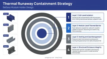
Thermal Runaway Containment
Holder and internal tray structures should be designed to slow inter-cell thermal propagation if a single cell fails:
- Fire-retardant polymer selection (V-0 rated materials) as the baseline
- Thermal barrier inserts — mica or ceramic pads between cell groups for higher-risk configurations
- Vent gas channels routed within holder geometry to direct hot gas away from adjacent cells toward the pack's pressure equalisation path
- Module-level containment features integrated into holder geometry to contain ejected material
Application-Specific Design Considerations
Different operating environments impose different design priorities — a single holder specification does not translate across applications.
| Application | Primary Design Drivers |
|---|---|
| Automotive EV | Crash loading, vibration, thermal cycling, UL94 V-0, IP67 |
| Railway / industrial | Repairability, cell replaceability, long service life |
| Drone / UAV | Minimum wall thickness, strict weight budget, vibration damping |
| Stationary energy storage | Chemical resistance, long-term UV and humidity stability |
IP Sealing Requirements
Tray sealing design is driven by target IP rating. Per IEC 60529:
- IP6X (dust-tight): no observable dust ingress after an 8-hour dust-chamber test
- IPX7 (immersion): 30-minute immersion with the lowest point 1,000 mm below water surface (for enclosures under 850 mm tall)
Sealing method selection (FIPG — Form-In-Place Gasket dispensed before mating, or CIPG — Cured-In-Place Gasket cured before assembly) depends on flange geometry, production rate, and sealing consistency requirements. Metallic components on marine or outdoor enclosures require saltwater-grade corrosion protection beyond base aluminium alloy selection.
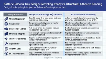
Design for Recycling and Serviceability
Physical design choices and end-of-life obligations are increasingly inseparable. EU Regulation 2023/1542 establishes sustainability requirements for batteries placed on EU markets — including recycled content targets, collection obligations, and carbon footprint rules. Compliance starts at the design stage, not after the component is specified.
Practical implications for holder and tray design:
- Prefer mechanical fastening over structural adhesive bonds where cell holders need to be replaceable
- Minimise material combinations that create incompatible recycling streams — for example, permanently bonding dissimilar polymer types
- Document material types explicitly for end-of-life sorting
Jairaj Group's engineering teams apply DFM and material optimisation review during component specification, which includes evaluating design-for-recycling requirements before tooling is committed.
Frequently Asked Questions
What materials are battery cell holders and trays made of?
Battery cell holders are primarily made from engineering polymers — PA66-GF, PP-GF, PC, and POM — selected for electrical insulation, dimensional stability, and UL94 V-0 flammability compliance. Battery trays are typically aluminium alloy (6061-T6 or 5052, extruded, stamped, or cast) or high-strength steel. GFRP composites are increasingly used for tray lids and covers.
What are the different types of battery cell holders?
Cell holders vary by format and scale:
- By cell format: precision-bored polymer grids (cylindrical), compression frames (prismatic), and rigid isolation frames (pouch)
- By scale: single-cell sleeves, multi-cell grid arrays, and CTP structural bonding frames that replace discrete holders entirely
What is the difference between a battery cell holder and a battery tray?
A cell holder positions and retains individual cells within a module, prioritising dimensional precision and electrical isolation. A battery tray is the structural lower enclosure of the complete pack — it carries all modules, interfaces with the vehicle chassis, and integrates thermal management and sealing functions.
What properties should a polymer battery holder have for EV applications?
EV polymer holders must meet several critical requirements:
- UL94 V-0 flammability rating
- Operating temperature tolerance above the cell's maximum, with margin
- Dimensional stability under thermal cycling (CTE matched to avoid retention failure)
- Mechanical strength compliant with vibration and shock standards
- IEC 60664-compliant creepage and clearance distances
How does cell format affect battery holder design?
Cylindrical cells need precision pocket arrays with controlled bore clearance. Prismatic cells need compression frames to manage swelling. Pouch cells — structurally flexible — require rigid supporting frames with integral swelling accommodation, compliant compression features, and electrical isolation of the conductive foil from adjacent cells and metal structures.
What manufacturing process is best for producing battery cell holders at scale?
Precision injection moulding is the preferred process for high-volume polymer cell holders. It delivers tight dimensional tolerances and complex geometries consistently across glass-fibre reinforced PA66 and PP grades, with PLC-controlled monitoring ensuring shot-to-shot repeatability. Achievable tolerances follow ISO 20457 and depend on part geometry, tool class, and resin characteristics.