This is the core financial risk DFM addresses. A design modification that costs almost nothing in a CAD file requires mold rework, cavity re-machining, or full tool replacement once tooling is committed — compressing schedule and inflating budget simultaneously.
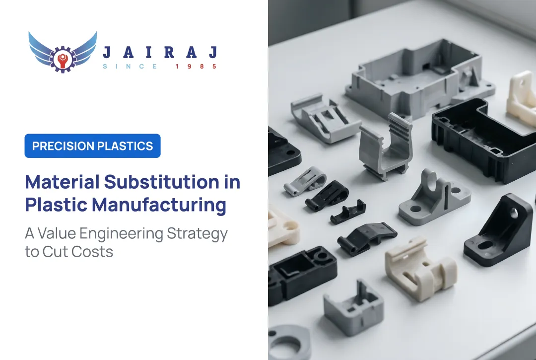
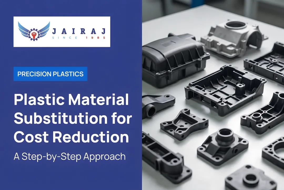
Plastic part manufacturing is not inherently expensive. Costs become excessive because of decisions made — or skipped — during design. This guide walks engineers through where those costs originate, what drives them, and how DFM principles eliminate avoidable spend across three dimensions: design decisions, process management, and manufacturing context.
Key Takeaways
- Most plastic part costs are locked in before production starts — geometry, features, and tolerances are the biggest levers engineers control
- Key cost drivers: non-uniform wall thickness, unnecessary undercuts, over-specified tolerances, poor material-process matching, and excessive part count
- DFM aligns part design with process requirements before tooling is committed, and changes at that stage cost a fraction of post-tooling corrections
- Gate placement, cooling channel design, draft angles, and mold flow simulation each carry direct per-unit cost impact
- Engaging a manufacturing partner during design, not after, prevents the most expensive DFM failures before they reach tooling
How Costs Around Plastic Parts Typically Build Up
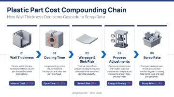
Plastic part costs rarely appear as a single visible line item. They accumulate as a chain of downstream consequences triggered by upstream design choices.
A wall thickness inconsistency that looks minor in CAD creates uneven cooling, which extends cycle time, which raises scrap rates — each adding fractional cost that compounds across thousands of production runs.
Covestro's engineering polymer design guide confirms that cooling time is proportional to the square of wall thickness, meaning even modest thickness variations carry outsized cycle time consequences.
Why These Costs Stay Hidden Until Volume
These costs are largely invisible during prototyping. A design that clears prototype validation can still carry:
- Latent cycle time penalties from suboptimal geometry
- Resin waste from poorly matched material choices
- Reject rate vulnerabilities that only surface under production volumes
- Inspection burden from over-specified tolerances
When these problems surface at scale, the root cause is almost always a design decision made months earlier — not a process failure on the production floor.
The Tooling Commitment Threshold
Tooling commitment is where latent design cost becomes locked-in production cost. Once molds are cut in steel, any design modification requires rework, cavity re-machining, or tool replacement. What cost nearly nothing to fix in a design file now carries significant financial and schedule consequences.
The cost to fix a design in CAD is effectively zero. The cost to fix the same issue in steel can run into lakhs, plus schedule delays. That gap is exactly why early DFM review pays back far more than it costs.
Key Cost Drivers in Plastic Part Manufacturing
Part Geometry Complexity
Features like undercuts, deep cavities, and non-uniform wall sections rank among the highest-impact cost drivers in injection molding. They require additional mold mechanisms: side-actions, lifters, and collapsible cores. Each adds tooling cost and extends cycle time through more complex ejection sequences.
Plastics Technology defines undercuts as features that prevent mold separation along the normal parting direction, requiring side-cores, internal lifters, stripping, or unscrewing mechanisms. These are direct cost consequences of geometry decisions made at the concept stage.
Non-uniform wall sections compound this: thicker areas cool more slowly, creating differential shrinkage that produces sink marks, warping, and internal stress, all of which increase scrap and require slower cycle times to manage.
Tolerance Over-Specification
Specifying tighter tolerances than the part's function actually requires forces:
- More expensive mold machining to achieve dimensional precision
- Slower cycle times to maintain consistency
- Higher inspection burden and more frequent rejection events
- Elevated scrap rates from conformance failures
According to SABIC's injection molding processing guide, holding close tolerances can significantly increase molded-part cost, and the practical minimum tolerance for neat amorphous resins is approximately ±0.002 in. for a 1 in. linear dimension. LANXESS similarly states that specifying tight tolerances can add manufacturing steps or require higher tooling costs.
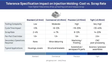
This is a decision-driven cost, not an inherent manufacturing constraint. Tolerances should reflect functional need, not engineering caution.
Material Selection Without Process Compatibility
Material choices made purely on performance data, without factoring in melt temperature, flow behavior, drying requirements, and cycle time implications, inflate per-unit cost in ways that don't appear until production begins.
Hygroscopic resins like nylon, polycarbonate, and polyester require thorough pre-drying to prevent degradation and surface defects. Reinforced composites typically require melt temperatures 17–33°C higher than unfilled resin, adding energy cost and cycle time.
A resin that marginally exceeds performance requirements but processes inefficiently costs more per unit than a well-matched alternative. That gap widens with volume.
Post-Processing and Assembly Dependencies
Designs requiring secondary operations (painting, bonding, mechanical assembly of separately molded components) embed costs that are consistently underestimated:
- Assembly labor and handling time
- Logistics and inventory for multiple part numbers
- Tolerance stack-up risk between mating components
- Additional inspection steps for assembled subassemblies
These costs are driven by design decisions that could have been resolved upstream through consolidation or integrated features.
Cost-Reduction Strategies Through DFM
DFM cost-reduction strategies fall into three categories based on where the cost originates: design decisions, process management, and the broader context of materials, supplier relationships, and timing.
Strategies That Reduce Costs by Changing Design Decisions
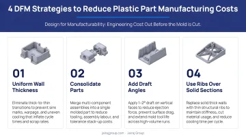
Design-stage choices about geometry, feature specification, part count, and tolerance assignment lock in the largest share of total cost before a single shot of plastic is injected — and they are fully within the engineer's control.
Standardise wall thickness: Inconsistent wall sections create differential cooling that produces sink marks, warping, and internal stress. Replacing thick walls with ribs or gussets achieves equivalent structural performance at lower material volume and shorter cycle time. The practical guideline: keep rib thickness at 50–60% of nominal wall thickness to prevent sink marks on the opposite face. BASF recommends approximately 50%, SABIC specifies 50–75%, and Covestro recommends 40–60% depending on resin type.
Eliminate or defer undercuts: Every undercut requires a side-action, lifter, or collapsible core — each adds tooling cost and cycle time. Redesigning features to be drafted away from undercut geometry, using pass-throughs, or repositioning parting lines can often eliminate undercuts without compromising function. Where undercuts are genuinely necessary, they must be planned during DFM — not discovered at tool qualification.
Consolidate parts: Designing multiple assembly components into a single moulded part eliminates assembly labour, reduces BOM part count, removes tolerance stack-up risks between mating parts, and simplifies inventory. Part consolidation is one of the highest-ROI DFM strategies for products with moderate to high production volumes.
Right-size tolerances to functional need: Audit every tight-tolerance callout and ask whether it directly affects the part's function or assembly fit. Tolerances tighter than what the process naturally achieves require slower cycle times, dedicated inspection steps, and more expensive tooling. Replacing over-specified tolerances with process-capable standards reduces cost without reducing performance.
Strategies That Reduce Costs by Changing How the Process Is Managed
Process-level decisions about tooling design, cooling, gating, and simulation reduce cost through better control and consistency. These strategies are most effective when addressed during the tooling design phase, before production is locked in.
Optimise gate placement and runner design: Gate location controls how molten plastic fills the cavity. Poor placement leads to weld lines, air traps, and cosmetic defects that generate scrap or require post-processing. Gate decisions should be made collaboratively between part designer and tooling engineer — not defaulted to convenience.
Design cooling channels for uniform heat extraction: Cooling accounts for approximately 70–80% of injection moulding cycle time, according to peer-reviewed conformal cooling research published in Polymers (Torres-Alba et al., 2020 and 2023). Improperly positioned or undersized cooling channels create hot spots, warping, and inconsistent shrinkage. Academic sources report conformal cooling can reduce cycle time by 30% to more than 50%, with one automotive part case achieving a 66% total cycle time reduction.
Ensure adequate draft angles and ejection planning: Insufficient draft angles create friction between part and mould surface during ejection, resulting in drag marks, surface damage, and accelerated mould wear. SABIC recommends at least 0.5° draft per side for unfilled compounds, with an additional 1° per 0.001 in. of texture depth for textured surfaces. Ejector pin placement that distributes force evenly prevents deformation at demoulding — both decisions directly affect reject rates and mould maintenance costs.
Run mould flow simulation before cutting steel: Simulation tools (mould flow analysis, FEA) allow engineering teams to predict fill behaviour, cooling uniformity, shrinkage patterns, and potential stress concentrations before any physical tooling is committed. Autodesk Moldflow and similar platforms identify weld lines, air traps, sink marks, and warpage risk at the digital stage. A single mould modification typically costs more than an entire simulation programme — making it one of the few DFM investments with a near-certain positive return.
Strategies That Reduce Costs by Changing the Context Around the Part
External factors — material ecosystem, supplier collaboration timing, and design review structures — influence cost not through the part design itself, but through the environment in which that design is realised.
Match resin to both performance requirements and process behaviour: Material selection should be evaluated on two axes: functional performance (mechanical, thermal, chemical) and process compatibility (melt flow, cycle time, drying requirements, mould material compatibility). A resin that technically meets performance specs but processes inefficiently costs more per unit than a well-matched alternative. Commodity resins — PP, ABS, HDPE — deserve serious evaluation before defaulting to engineering-grade materials. The performance gap is often narrower than assumed; the processing cost gap is often wider.
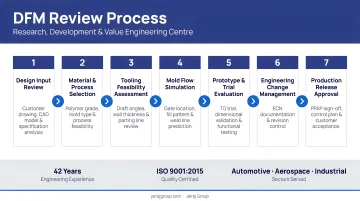
Engage manufacturing expertise during design, not after: The single highest-impact context decision is when manufacturing input enters the design process. Designs reviewed by an experienced injection moulder during concept or detailed design stages catch geometry, tolerance, and material issues before they become tooling problems. Jairaj Group's Research, Development & Value Engineering Centres provide structured DFM review covering flow analysis, cooling optimisation, warpage prediction, and design-to-process alignment — with in-house tool room capabilities across six manufacturing facilities. Engaging that review before tooling is committed is where the most expensive DFM failures get stopped.
Rationalise surface finish and cosmetic specifications: Surface texture, gloss levels, and cosmetic callouts have direct implications for mould polishing cost, required draft angles, and maintenance frequency. Cosmetic specifications that exceed what end-use function or customer experience requires inflate tooling and production cost without adding engineering value. Specifications should be differentiated by surface visibility and contact — non-cosmetic surfaces should carry standard, process-friendly finishes.
Conclusion
Reducing plastic part manufacturing costs through DFM is fundamentally about identifying where cost originates — in design decisions, process management, or context — and addressing those origins deliberately, rather than applying blanket cost-cutting measures that risk compromising quality or performance.
Engineers who consistently reduce cost without compromising quality share a few common habits:
- Treat design as a manufacturing decision from day one
- Revisit DFM assumptions as volumes, materials, or supplier relationships change
- Engage manufacturing partners early — their polymer expertise shapes design outcomes, not just production ones
That last point matters more than it often gets credit for. A supplier with deep process knowledge contributes to cost reduction before a single part is cut.
Frequently Asked Questions
What is the impact of DFM on cost, quality, and time?
DFM simultaneously reduces cost by eliminating avoidable tooling and process complexity, improves quality by aligning part geometry with process capability, and compresses time-to-market by preventing design rework cycles before or after tool qualification. All three benefits reinforce each other: better geometry produces fewer defects, and fewer defects mean faster delivery.
What are the most common design mistakes that increase plastic part costs?
The most frequently cited design-origin cost drivers are non-uniform wall thickness, unnecessary undercuts, over-specified tolerances, excessive part count requiring assembly, and material selection made without considering processing compatibility. Each of these is a controllable decision, not an inherent manufacturing constraint.
When in the product development process should DFM analysis be applied?
DFM is most valuable — and least expensive to act on — during concept and detailed design stages, before tooling is committed. Post-tooling DFM reviews are still useful for identifying process optimizations, but any design changes identified at that stage carry significantly higher implementation cost than equivalent changes made in a design file.
Does DFM apply to low-volume plastic part production as well as high-volume?
DFM's per-unit savings scale with volume, but tooling investment and defect-risk reduction matter equally at low volumes. A poorly designed tool for a small production run still carries the full cost of mold modification if issues surface during qualification.
How do wall thickness and draft angles affect injection molding cost?
Non-uniform wall thickness creates differential cooling that increases cycle time and defect rates, including sink marks, warping, and internal voids. Insufficient draft angles increase ejection force, mold wear, and surface damage — both are design variables with direct impact on per-unit cost and mold maintenance frequency.
What is part consolidation in DFM and how does it reduce costs?
Part consolidation means redesigning multiple separately manufactured components into a single molded part. This eliminates assembly labor, reduces inventory complexity, and removes tolerance stack-up between mating parts, making it one of the highest-return DFM strategies for products with recurring assembly operations.