Introduction
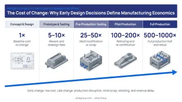
A design change made on paper costs almost nothing. The same change after tooling steel has been cut can cost 10 to 1,000 times more, depending on the stage at which it surfaces — a range documented across Boothroyd Dewhurst's DFMA research and widely referenced in manufacturing engineering practice.
A single undercut left unresolved until the first tool trial can trigger mold rework, push launch timelines by weeks, and compress margins on every part produced afterward. These costs don't appear once — they accumulate across every production run that follows.
Most of these costs are avoidable. They are not inherent to the material or the process — they originate in design-stage decisions: geometry choices, material selections, tolerance calls, and cooling assumptions that each carry a downstream price when left unexamined.
The sections below break down which decisions carry the highest cost risk — and what engineers can do about them before the first tool is cut.
Key Takeaways
- Plastic part costs compound across design decisions — geometry, material, tooling, and post-processing — not as a single line item
- The four primary cost buckets are: material waste, tooling complexity, cycle time, and secondary processing
- DFM delivers the most value before tooling steel is cut; correction costs rise steeply at every subsequent stage
- Cost is governed by three levers: early design decisions, production governance, and the tools and supplier relationships that support both
- Involving your molder at the concept stage, before design freeze, is consistently the highest-return action available
How DFM Costs Build Up in Plastic Parts
Injection moulding costs don't announce themselves at the design stage. They build up across a chain of decisions, each one constraining the next.
A geometry choice in CAD creates a tooling constraint that extends cycle time. Across thousands of production runs, that added time compounds — eventually surfacing as scrap, rework, or a launch delay. By that point, the originating design decision is several steps removed and rarely identified as the cause.
Why the Build-Up Stays Invisible
Non-uniform wall thickness is a useful example. A part with inconsistent walls doesn't fail visibly in CAD. It passes early design reviews. The cost penalty only appears during cooling — when differential shrinkage creates warpage or sink marks that weren't predicted, and when cycle time runs longer than target across the full production run.
DFMA research from Boothroyd Dewhurst indicates that approximately 80% of manufacturing cost is determined at the design stage — before any production begins. That figure has caveats (MIT working paper research notes it's difficult to trace to a single authoritative source), but the directional reality is well-supported: the later a design issue surfaces, the more embedded it becomes in cost structure, and the more expensive it is to correct.
The Cost-of-Change Slope
The cost escalation by development phase is steep:
| Development Phase | Relative Cost of Change |
|---|---|
| Concept design | 1× |
| Detailed design | ~10× |
| Post-tooling | ~100× |
| Production | ~1,000× |
These figures reflect the DFMA methodology framework. A DFM issue resolved at the CAD stage costs hours of engineering time. The same issue resolved after the mould is built may require weld repairs, insert replacements, or full mould rework — plus the downstream cost of delayed parts.
Key Cost Drivers in Plastic Part DFM
Three categories of design decisions generate the majority of avoidable cost in injection-molded parts.
Part Geometry Complexity
Undercuts that require side actions or lifters, non-uniform wall thicknesses, and deep cavities with insufficient draft angles each add cost at two levels: tooling complexity and per-cycle production time.
Side actions for undercuts, for example, add mechanical complexity to the mold and require ongoing maintenance. According to Protolabs' cost analysis, cams or inserts typically add $1,000–$2,000 USD per component to mold price (roughly ₹83,000–₹1,66,000). These are costs that compound across every tooling iteration and maintenance cycle.
The critical point: most geometry-driven cost drivers are the result of design choices, not process limitations.
Material-Process Mismatch
Polymers selected purely for end-use performance — strength, thermal resistance, chemical compatibility — without considering mold flow behavior introduce manufacturing costs that surface only in production:
- Drying requirements for hygroscopic resins (nylon, PC) add process steps and process window risk
- High-shrinkage materials require tighter process control and increase dimensional variation
- Narrow processing windows reduce production efficiency and raise scrap rates
- Some high-performance resins require specialized tooling steels, increasing tooling cost
Each of these factors increases per-part cost and process variability — which is why material selection and DFM review need to happen in parallel, not in sequence.
Tolerance Over-Specification
Tolerances tighter than function requires are a direct cost driver that rarely gets flagged in design review. Tighter tolerances force mold makers into higher-precision machining, increase inspection time, and raise scrap rates — often on features where dimensional variation has no functional consequence.
The numbers make this concrete. For context: SPI/AQ-102 commercial tolerances for ABS run approximately ±0.003 in/in, with fine tolerances at ±0.002 in/in — material-specific, not universal. Specifying tolerances significantly beyond these thresholds on non-critical features adds cost with no corresponding functional return. The decision to tighten a tolerance should always be deliberate, tied to a specific functional requirement at a defined mating surface.
Cost-Reduction Strategies for DFM in Plastic Parts
DFM cost reduction doesn't follow a single playbook. Where cost originates determines which strategies apply — some require changing design decisions before tooling, others require better production governance, and still others address the broader system of supplier relationships, simulation tools, and tooling investment decisions.
Strategies That Reduce Costs by Changing Design Decisions
These are the highest-impact interventions because they set the constraints under which every downstream cost operates. Changes here cost least and yield the most.
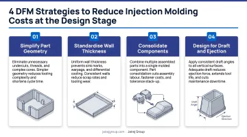
Standardize wall thickness and use structural geometry instead of mass. Replacing thick walls with uniform, nominal-thickness walls supported by ribs reduces material usage, shortens cooling time, and eliminates sink marks. The standard DFM guideline: rib thickness should be 50–60% of adjacent wall thickness to prevent sink (Covestro); for appearance-critical surfaces, BASF recommends no more than 50% for textured and 30% for untextured outer surfaces.
Eliminate undercuts through geometry redesign before adding tooling mechanisms. Many undercuts can be resolved by reorienting parting lines, using pass-through designs, or simplifying attachment geometry — without adding side actions or lifters. Reserve tooling mechanisms for undercuts that genuinely cannot be resolved at the design level.
Right-size tolerances to what function actually requires. Tolerances beyond the SPI commercial range on non-critical features drive mold machining cost, inspection cost, and scrap — with no functional return. Apply tighter tolerances only where a specific mating or assembly requirement demands them.
Consolidate parts to reduce the bill of materials. Each additional plastic component adds its own tooling investment, assembly labor, and tolerance stack-up risk. Across 170+ DFMA case studies, Boothroyd Dewhurst documented an average 54% part-count reduction and 50% total cost reduction — numbers that reflect how much cost accumulates across tooling, assembly, and scrap when part counts go unexamined.
Strategies That Reduce Costs by Changing How Production Is Managed
Once a design moves toward tooling, cost reduction depends on how well the transition is governed.
Run mold flow simulation before steel is committed. Tools like Moldflow and SolidWorks Plastics identify fill imbalance, weld line locations, warpage risk, and packing pressure requirements digitally — at a fraction of the cost of a tooling revision. Jairaj Group's engineering centers run flow analysis, cooling optimization, and warpage prediction specifically to validate tooling decisions before physical tools are cut.
Treat DFM review as a formal design gate, not an informal check. DFM reviews conducted after design freeze cost significantly more to act on than reviews built into the development milestone process. A practical minimum: establish a DFM sign-off requirement before any tooling purchase order is issued.
Design cooling as a DFM variable. Peer-reviewed research confirms that cooling accounts for 50–80% of total injection molding cycle time. Poorly positioned cooling channels compound their cost across every production cycle. Conformal cooling, where applicable, has been shown to reduce cycle time by approximately 30% compared to conventional channels. Baffle placement, channel diameter, and proximity to part geometry should be evaluated at the DFM stage — not left as mold maker discretion.
Strategies That Reduce Costs by Changing the Context Around the Part
In many programs, the greatest cost reduction opportunities sit outside the part geometry itself — in the system of decisions surrounding material selection, supplier engagement, and tooling investment.
Engage your injection molder as a design partner, not a downstream vendor. Manufacturers with in-house tool room capabilities and deep polymer expertise can identify geometric, material, and tooling risks at the concept stage, before any capital is committed. Jairaj Group's engineering support includes DFM analysis, process simulation, and material validation — structured to catch tooling and geometry risks before the first tool is cut rather than after.
Match material selection to manufacturability alongside application performance. A resin chosen purely for mechanical or thermal properties may carry hidden manufacturing costs — drying requirements, narrow processing windows, higher cycle times, or compatibility constraints with available tooling steels. Material selection should be a joint decision involving DFM criteria from the outset, not just end-use specification.
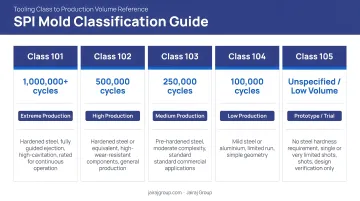
Align tooling class and cavity count with realistic production volumes. Tooling over-specified for actual volumes wastes budget that could fund design refinement. Under-specified tooling for high-volume programs creates early wear, dimensional drift, and maintenance costs. As a rough guide based on SPI mold classification standards:
| SPI Mold Class | Typical Production Volume |
|---|---|
| Class 105 | Up to 500 cycles (prototype) |
| Class 104 | 501–100,000 cycles |
| Class 103 | 100,001–500,000 cycles |
| Class 102 | 500,001–1,000,000 cycles |
| Class 101 | Over 1,000,000 cycles |
Matching tooling class to realistic annual volume — not aspirational volume — prevents both under-investment and over-investment in tooling capital.
Conclusion
Effective DFM cost reduction starts with knowing where cost actually originates — whether that's a wall thickness call made in CAD, a material spec added without process context, or a tolerance that doubled tooling complexity. Blanket cost-cutting without that root-cause clarity tends to shift costs rather than eliminate them, often surfacing as scrap, rework, or tool modifications downstream.
The most durable improvements come from teams that treat DFM as an ongoing discipline — built into design reviews, not bolted on at the end. Bringing the manufacturer into conversations at the concept stage, before geometry is locked, consistently yields more actionable feedback than a pre-production audit ever can. That upstream collaboration is where real cost is saved.
Frequently Asked Questions
What is DFM in molding?
DFM (Design for Manufacturability) in molding is the practice of designing plastic parts with the injection molding process in mind — optimizing geometry, material choice, and tolerances so the part can be produced consistently, efficiently, and at the lowest viable cost from the start. It shifts problem-solving from the production floor to the design stage, where changes are quick to implement and low-cost to execute.
What is the impact of DFM on cost, quality, and time?
Effective DFM simultaneously reduces tooling and per-part costs, improves dimensional consistency and defect rates, and shortens time-to-market by preventing design revisions after tooling is committed.
When in the product development process should DFM be applied?
DFM should be applied at the concept and CAD design stage, before any tooling decisions are made, and revisited at each design milestone. The cost of addressing a DFM issue rises sharply at every phase, making early application the point where changes have the greatest impact and the lowest cost.
What are the most common and costly DFM mistakes in plastic part design?
The most common mistakes are non-uniform wall thickness, unnecessary undercuts, over-specified tolerances on non-functional features, and inadequate draft angles. All of these tend to go undetected as cost drivers until tooling trials surface the problem, at which point correction carries a steep price.
How does wall thickness affect injection molding costs?
Non-uniform or excessive wall thickness increases cooling time (extending cycle time across every part produced), increases material consumption, and raises the risk of sink marks and warping — all of which compound in cost at scale. Uniform walls supported by structural ribs are the standard DFM approach for managing these cost drivers.
Can DFM reduce tooling costs for injection molded parts?
Yes — DFM directly reduces tooling costs by eliminating features that require complex mechanisms (such as side actions for undercuts), simplifying parting line geometry, and right-sizing tolerances. Each of these changes reduces machining complexity, tooling build time, and the likelihood of costly revisions after first article trials.