Introduction
DC-DC converters are increasingly deployed in high-stress environments — automotive underhood systems, EV powertrains, industrial motor drives — where the plastic housing is not a passive shell but an active part of the converter's thermal and protection system. A poorly chosen housing material or a badly designed enclosure can undo even the most carefully engineered power circuit.
That failure point rarely gets attention. Most design resources focus exclusively on circuit-level choices — topology, control scheme, inductor sizing — leaving engineers without practical guidance on enclosure materials and housing-level thermal management.
This guide covers the enclosure decisions that determine whether a converter survives in the field:
- Material selection criteria for DC-DC converter plastic housings
- Thermal management strategies at the enclosure level
- Key structural and mechanical design considerations
- How these choices vary across automotive, EV, and industrial applications
Key Takeaways
- Choosing the right plastic housing material determines thermal dissipation capacity, dimensional stability under load, and overall converter service life
- PBT, PA66-GF, and PPS outperform commodity plastics; UL94 V-0 flame retardancy is a standard design target for power electronics enclosures
- Thermal management requires thermally conductive polymer grades, TIM pads, external fin geometry, and insert-moulded metal base plates
- IP rating, CTE mismatch with metal inserts, and EMI shielding all require attention at the earliest design stage, before tooling is committed
Why the Housing Matters
Heat Is the Core Problem
DC-DC converters lose power through switching and conduction losses. Even a high-performing design — like the 3 kW, 14V/215A EV auxiliary converter documented in IEEE research achieving 95.1% full-load efficiency — still generates meaningful heat within a compact sealed enclosure. That heat must exit through the housing.
When it doesn't, the consequences compound quickly:
- Efficiency degrades as semiconductor junction temperatures rise
- Component derating forces the converter to operate below rated power
- Electrolytic capacitor lifespan collapses — Nichicon's lifetime data confirms that capacitor chemical reaction rate doubles for every 10°C rise in temperature
- Seal and gasket distortion accelerates under sustained thermal load
The housing is not packaging. It is a functional heat pathway.
Two Functions That Can Conflict
The enclosure must simultaneously:
- Protect against mechanical shock, vibration, moisture, dust, and chemical ingress
- Dissipate heat by conducting thermal energy away from internal components
These two roles can work against each other. Sealing for IP67 raises internal thermal resistance. Thicker walls improve structural rigidity but slow heat transfer. Treating sealing, structural performance, and thermal management as coupled problems — not independent checkboxes — is what produces an enclosure that holds up across service life.
Market Context
Scale makes these tradeoffs consequential. MarketsandMarkets projects the automotive DC-DC converter market to grow from USD 6.20 billion in 2025 to USD 18.75 billion by 2035, at an 11.7% CAGR. As EV onboard converters and industrial drives push higher power densities into smaller packages, the thermal demands on enclosures are rising — and housing designs that cannot manage that heat become the failure point, regardless of how well the electronics perform.
Choosing the Right Plastic: Key Material Properties
Critical Thermal Properties to Evaluate
Two thermal properties should screen every candidate material before anything else:
- Heat Deflection Temperature (HDT): The housing must retain its shape under mechanical load across the full operating range. For automotive and EV applications, this means -40°C to +125°C continuous, with transient peaks beyond that. A material whose HDT sits only marginally above operating temperature will creep under sustained gasket compression and cause seal failure.
- Continuous Use Temperature (CUT) / RTI: HDT is a short-term snapshot. Continuous use temperature — expressed as UL Relative Thermal Index (RTI) — governs long-term service life. The two values are not interchangeable.
Beyond temperature ratings, thermal conductivity determines whether the housing helps or hinders heat dissipation. Standard engineering plastics are poor conductors: PBT runs around 0.27 W/m·K, PA66-GF30 around 0.36 W/m·K, and PC between 0.20–0.25 W/m·K — they insulate more than they conduct.
Thermally conductive filled grades (boron nitride, alumina, or graphite-filled) reach 1–10 W/m·K for electrically insulating grades, with specialist compounds exceeding that range. These are warranted when power dissipation density inside the enclosure exceeds what convection and fin geometry alone can handle.
Top Engineering Plastics for Converter Housings
Use this decision framework when selecting a base material:
| Material | HDT (1.8 MPa) | CUT / RTI | Key Strength | Key Limitation |
|---|---|---|---|---|
| PBT (unfilled) | ~55°C | 135°C | Chemical resistance, easy processing | Low HDT limits high-temp use |
| PBT-GF30 | ~205°C | 150°C | Dimensional stability, flame-retardant grades available | Moderate CTE mismatch |
| PA66-GF30 | ~250°C | 140°C electrical | High strength, good heat resistance | Moisture absorption (up to 1.9% at humidity) must be managed |
| PC | ~124–132°C | 130°C | Impact strength, design flexibility | Moderate upper temperature ceiling |
| PPS (reinforced) | >260°C | 200–240°C | Rated to 200–240°C continuous; excellent chemical resistance, 0.03% moisture absorption | Higher material cost, processing demands |
| LCP | 120–340°C by grade | 130°C+ | Extreme precision, low CTE | Cost, limited forming options |
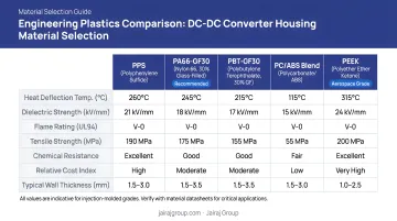
Flame retardancy is a standard design target for power electronics enclosures due to proximity to live conductors. UL94 V-0 is the typical goal, though the specific product standard, OEM specification, or UL file ultimately defines the requirement.
Halogen-free flame-retardant (HFFR) grades — such as PBT compounds using Exolit OP additives at roughly 18 wt% loading — can achieve V-0 while meeting RoHS/REACH requirements. Note that FR additives can reduce impact strength and affect mould flow; processing parameters must account for this.
CTE mismatch is a chronic failure mode in insert-moulded converter housings. Unfilled PBT has a CTE around 115×10⁻⁶/K, while aluminium 6061-T6 sits at approximately 25.2 µm/m·°C. Over repeated thermal cycles, this differential causes micro-cracking at metal-plastic interfaces and gasket distortion. Glass-fibre reinforcement significantly closes this gap — PPS-GF40 achieves approximately 21 µm/m·°C parallel to flow — making reinforced grades essential wherever metal inserts are integrated.
Thermal Management in Plastic Housings
Passive Thermal Design Strategies
Wall thickness is the first lever. Thinner walls reduce thermal resistance to the environment but must maintain structural rigidity and IP seal integrity under assembly torque and vibration loading. That trade-off is difficult to optimise on paper alone: FEA thermal simulation before committing to tooling identifies localised hot spots near high-dissipation components like switching FETs before they become a re-tooling problem.
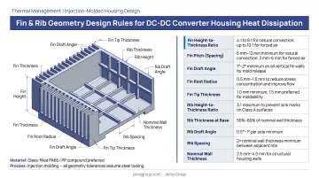
External fin and rib geometry increases convective surface area without adding weight. Key design rules:
- Orient fins vertically to support natural convection airflow
- Space fins approximately 6–10 mm apart to prevent stagnant air zones — Wakefield Thermal guidance suggests roughly ¼ inch (approximately 6 mm) spacing for natural convection
- Maintain adequate base thickness to conduct heat from the housing wall to the fin roots
- Design draft angles compatible with the moulding direction to ensure clean ejection
Venting offers a thermal benefit but conflicts with IP requirements. The practical middle ground: IP-rated vent membranes (Gore-type adhesive vents) allow pressure equalisation and moisture management while maintaining protection ratings. Specify them when sealed-housing thermal resistance pushes component temperatures past derating limits.
Thermally Conductive Interface Solutions
Plastic alone cannot do the thermal work. Thermal interface materials (TIMs) — gap-filling pads, phase-change materials, or thermally conductive potting compounds — couple heat from PCB components to the housing base wall. An air gap between the PCB and housing base creates significant thermal resistance; a well-applied conformable gap pad eliminates that resistance entirely. Dow's DOWSIL TC-5628, for example, reaches 4.0 W/m·K, roughly 13–40× higher than unfilled engineering plastics, which typically range from 0.1–0.3 W/m·K.
Insert-moulded metal base plates represent the strongest thermal solution within a plastic enclosure architecture. An aluminium or copper base is over-moulded with engineering plastic side walls, combining:
- Metal's thermal conductivity at the heat-generating interface
- Plastic's weight savings, electrical isolation, and design freedom for the enclosure body
This hybrid construction is particularly effective for sealed EV onboard converters where both IP67 compliance and aggressive thermal management are required simultaneously. Jairaj Group's insert moulding and overmoulding capabilities are well-suited to this architecture, integrating metal thermal spreaders within precision-moulded enclosure structures for EV and industrial converter applications.
Structural and Design Considerations
Injection Moulding Design Rules That Affect Performance
Enclosure performance starts with mould design fundamentals:
- Uniform wall thickness prevents warpage and sink marks that distort sealing surfaces
- Draft angles of at least 1° per inch of cavity depth (per Protolabs guidance) ensure clean ejection without surface damage
- Rib-to-wall thickness ratios of approximately 40–60% prevent sink marks on the outer surface opposite each rib — critical where ribs back a gasket sealing face
Sealing surface flatness is not a cosmetic requirement. A warped mating face allows IP seals to leak under even small amounts of housing deflection.
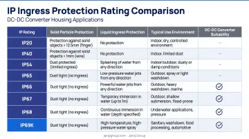
IP Ingress Protection Design
IP rating requirements are application-driven:
| Environment | Typical IP Target | Sealing Method |
|---|---|---|
| Indoor industrial panel | IP54 | Foam gasket, snap-fit cover |
| Outdoor / transportation | IP65 | O-ring groove, ultrasonic weld |
| Automotive underbody / EV | IP67 | O-ring with retention groove, overmoulded cable entries |
Housing geometry determines achievable IP class. O-ring groove depth and width must be matched to the ring cross-section and compression ratio. Ultrasonic weld joint geometry — energy director profile, wall alignment — directly affects bond strength and leak integrity. Validation through real-time weld monitoring and post-process ingress testing is the standard for confirming seal integrity in production — not just during design sign-off.
EMI/RFI Shielding Integration
Achieving IP protection addresses liquid and particulate ingress. EMI is a separate and equally critical threat. Switching DC-DC converters are strong EMI sources, and plastic housings provide no inherent shielding — an explicit shielding strategy must be specified:
- Conductive spray coatings (such as Parker PRO-SHIELD): 60+ dB shielding effectiveness, applied to housing interior after moulding
- Conductive plastic compounds: reach up to 85 dB, though they reduce impact strength and typically require wall thickness adjustments to compensate
- Metal shielding inserts: highest effectiveness (85–100 dB per Laird data), but add weight and assembly steps
Compliance targets — FCC Part 15 for North American markets, CISPR 25 for automotive (150 kHz to 5,925 MHz) — should be defined before housing material and geometry are finalised.
Precision Insert Moulding for Power Electronics
Insert moulding integrates grounding studs, mounting bosses, threaded inserts, and connector interfaces during the moulding cycle. Benefits in automotive and EV converter housings:
- Eliminates post-assembly fastener steps
- Improves positional accuracy of ground paths and connector mating features
- Reduces loosening risk under high-vibration underhood conditions
Holding tight tolerances on insert placement while maintaining consistent thin-wall sections requires both tool room precision and closed-loop process control. Jairaj Group's in-house tool room supports multi-cavity, insert, and two-shot moulding with PLC-controlled machinery and real-time cavity monitoring — capabilities that matter most when insert position and wall uniformity must be achieved in the same shot.
Material Selection by Application
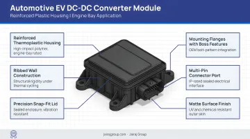
Automotive and Electric Vehicles
Automotive DC-DC converter housings — 12V auxiliaries, 48V mild-hybrid systems, onboard EV chargers — face the harshest combination of requirements:
- Temperature range: -40°C to +125°C continuous, with transient excursions higher
- Fluid exposure: coolant, oil mist, cleaning agents — per ISO 16750 environmental conditions for vehicle-mounted electronics
- Long-term durability: ZVEI robustness validation examples reference 10–15 year lifespans and 200,000–600,000 km mileage targets; specific targets vary by OEM programme
Recommended materials: PPS (reinforced) or PA66-GF35 as primary choices. PPS provides the highest chemical resistance and dimensional stability; PA66-GF35 offers cost efficiency where fluid exposure is moderate. Both must be specified in flame-retardant grades for underhood use.
Jairaj Group manufactures PA66-GF and PPS-grade housings for automotive OEM programmes — including EV-focused applications — across its production facilities in Manesar, Pune, and Gujarat.
Industrial and Electronics Applications
Industrial DC-DC converter housings — motor drives, PLCs, robotics, power distribution panels — typically face less severe temperature extremes but have their own priority set:
- UL and IEC certification compliance (IEC 62477-1 applies to power electronic converter systems)
- Chemical resistance to industrial cleaning agents and cutting fluids
- Cost efficiency at volume
For general industrial enclosures, flame-retardant PBT-GF30 is the standard choice. Where impact resistance and surface finish are priorities, PC/ABS blends offer a practical alternative. Jairaj Group processes PA66-GF and PC materials for industrial enclosure applications under its ISO 9001:2015 quality system.
Material selection across both segments ultimately comes down to the same trade-off: matching thermal performance and chemical resistance to the application environment without overspecifying — and therefore overpricing — the housing.
Frequently Asked Questions
How do I size a DC-to-DC converter?
Start with required output power (Vout × Iout), then divide by expected efficiency to find input power demand. Add a 20–30% safety margin to handle transient loads and account for efficiency degradation over service life.
What are the main types of DC-to-DC converters?
The four primary topologies are buck (steps voltage down), boost (steps voltage up), buck-boost (handles both directions), and isolated converters such as flyback and forward types, which provide galvanic isolation between input and output.
What are DCM and CCM in DC-to-DC converters?
In CCM (Continuous Conduction Mode), inductor current never reaches zero, which keeps ripple low at full load. In DCM (Discontinuous Conduction Mode), current resets to zero each cycle, making it common at light loads but with higher peak currents and ripple.
What plastic material is best for a DC-DC converter housing?
PBT or PA66-GF for general industrial applications; PPS for high-temperature automotive or chemically aggressive environments. Non-negotiable baselines: UL94 V-0 flame retardancy as a design target, and an HDT well above the converter's maximum continuous operating temperature.
How do you manage heat in a sealed plastic DC-DC converter housing?
Specify thermally conductive polymer grades or insert-moulded metal base plates for the heat path, apply TIM pads between the PCB and housing base, optimise wall thickness for thermal resistance, and add external fin geometry for convective dissipation. Each step must be validated without compromising the IP seal.
What IP rating does a DC-DC converter housing typically need?
IP54 suits general indoor industrial panels; IP65 covers dust-tight, water-jet-resistant outdoor and transportation use; IP67 is required for automotive underbody and EV installations, with submersion protection to 1 metre for 30 minutes. The target IP class should drive housing geometry and sealing method from the first design iteration.