Introduction
The inside of a spinning tyre at highway speeds is among the harshest service environments any plastic component will face.
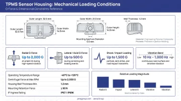
A TPMS sensor housing must endure radial accelerations exceeding 200 G at 120 km/h, shock pulses up to 5,000 G, temperatures ranging from sub-zero winters to peak summer heat, and continuous exposure to tyre sealants, inflation lubricants, and road contaminants.
Get the material selection wrong and the consequences compound quickly. Premature housing failure compromises sensor accuracy, triggers false warnings, and can escalate into field failures that strain OEM relationships and invite recalls. With FMVSS No. 138 mandating TPMS fitment across all new light vehicles, every housing specification decision carries real risk.
What follows is a practical guide to the primary plastic candidates, the selection criteria that go beyond mechanical datasheets, and the manufacturing considerations that determine which material actually works for a given TPMS design.
TL;DR: Quick Reference for TPMS Housing Material Selection
- PA66 and PPS are the most widely specified plastics — PA66 for cost-sensitive applications, PPS where thermal and chemical resistance take priority
- Hygroscopic nylons absorb moisture, causing dimensional swell that compromises sensor fit and sealing integrity
- RF signal transparency is frequently underestimated: validate dielectric properties on final moulded parts, not datasheets alone
- Glass fibre reinforcement improves stiffness but raises dielectric constant and loss tangent, affecting signal transmission based on fibre orientation
- Material selection and process design must be decided together — mould flow, wall thickness, and crystallisation behaviour all constrain viable candidates
The Harsh Reality: Operating Conditions TPMS Housings Must Survive
Before evaluating materials, engineers need a clear picture of what the housing actually faces in service. The loading environment is genuinely multi-axis and simultaneous — not sequential. Three distinct stress categories define the qualification baseline: mechanical loading, thermal and chemical exposure, and moisture combined with vibration.
Centrifugal and Shock Loading
At 120 km/h, TPMS sensor modules experience radial accelerations typically above 200 G, rising further at higher vehicle speeds. The same module must survive a 5,000 G shock pulse from pothole or kerb strike events. These figures come from published energy harvesting research on TPMS modules, which characterises typical module dimensions of 40–60 mm tangential length and a maximum weight of approximately 25 g. Those dimensional constraints tightly limit housing mass while demanding high specific strength from the chosen material.
Snap-fit retention features and integrated clips are particularly vulnerable under centrifugal loading. Creep and fatigue behaviour under sustained and cyclic stress loads are more relevant design-limiting factors than static tensile strength.
Thermal and Chemical Exposure
The standard automotive service range cited across the industry is –40°C to +125°C for continuous exposure, with peak excursions potentially higher depending on wheel position and vehicle duty cycle.
EV platforms add a further layer of thermal complexity. Heavier vehicle masses generate more tyre heat, and battery thermal management proximity in certain architectures can push wheel-area temperatures beyond conventional ICE baselines.
Chemical exposure compounds the thermal challenge. A housing encounters:
- Tyre sealants (typically glycol-based or latex formulations)
- Inflation lubricants used during tyre mounting
- Nitrogen/oxygen inflation blends
- Road salt, brake dust, and contaminated water ingress
Published chemical resistance data covers individual reagents. In service, the housing faces mixtures at elevated temperature — a combination that degrades materials more aggressively than single-reagent charts suggest. This must be accounted for in qualification testing.
Moisture and Vibration
Continuous broadband vibration from road surfaces combines with episodic mechanical shock from impacts. Fatigue behaviour under cyclic stress is a distinct concern from static strength: a material's room-temperature tensile strength reveals nothing about crack propagation behaviour after 10 million vibration cycles.
Hygroscopic housing materials also present a sealing challenge: moisture absorption causes dimensional change at the sealing interface, which can compromise IP-rated ingress protection over time.
The Main Contenders: Plastic Materials Used in TPMS Sensor Housings
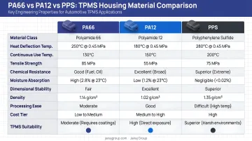
Polyamide 66 and Polyamide 12 (PA66 / PA12)
PA66 remains the most widely used TPMS housing material in cost-driven mainstream applications. Glass-filled grades such as BASF Ultramid A3WG6 HRX offer good mechanical stiffness and a heat deflection temperature of 245°C at 1.8 MPa — more than adequate for most wheel-area thermal conditions.
The primary limitation is hygroscopicity. BASF's published data for this grade shows equilibrium moisture absorption of 1.5–1.9% at 23°C/50% RH, rising to 5.6–6.3% at water saturation. In the humid environment inside a tyre, this translates to dimensional swell that can affect close-tolerance sensor fits and alter the geometry of sealing surfaces.
PA12 addresses this directly. Its moisture absorption is roughly one-third that of PA66, giving significantly better dimensional stability across the service temperature and humidity range. PA12 carries a modest cost premium, but for designs where sensor fitment tolerance or sealing integrity is tight, that premium is often justified by reduced warranty exposure.
When performance requirements push beyond what nylons can deliver, engineers typically look at PPS.
Polyphenylene Sulfide (PPS)
PPS is increasingly the material of choice for demanding TPMS applications. Key advantages over PA-family materials:
- Near-zero moisture absorption, giving dimensionally stable housings regardless of ambient humidity
- Inherent chemical resistance to glycols, fuels, and alkalis (confirmed for grades such as Syensqo Ryton R-4-230NA)
- UL94 V-0 flammability rating without flame-retardant additives (confirmed for Celanese Fortron 1140L4 at 40% GF)
- Heat deflection temperature typically above 260°C for glass-filled grades, well above PA66
The trade-offs are worth understanding before committing:
- More abrasive on tooling than nylon, requiring careful mould temperature control to manage warpage
- Material cost substantially higher than PA66
- Stiffness that benefits housing geometry retention also leaves less snap-fit deflection margin before fracture, compared to the more ductile nylons
POM (Acetal) and LCP
POM offers excellent dimensional stability, low friction, and tight tolerance capability. Its weakness in this application is susceptibility to strong acids and certain solvents present in tyre sealant formulations, which limits its use to lower-chemical-exposure housing zones or designs with alternative sealing architectures.
LCP (Liquid Crystal Polymer) sits at the high end of the performance spectrum. LCP excels at thin-wall flow, sustained high-temperature operation, and — critically — RF transparency. Published dielectric data from the Celanese Vectra design guide shows Vectra A130 (30% GF) at a relative permittivity of 3.2 at 1 GHz and a loss tangent of 0.006 at 1 GHz, among the best RF performance figures available for reinforced engineering polymers. The CLTE is also tightly controlled, at 5 × 10⁻⁶/°C in the flow direction.
LCP sees limited TPMS adoption outside high-specification applications, mainly due to cost. It appears most often in motorsport-adjacent or premium-tier designs where RF performance and dimensional precision justify the premium.
Critical Selection Criteria: What Engineers Must Evaluate Beyond Mechanical Data
RF Signal Transparency
TPMS sensors transmit at either 315 MHz (North America) or 433 MHz (Europe and most other markets). The housing sits directly in the signal path, and a material with poor dielectric properties will attenuate that signal, reducing read range or causing intermittent detection.
Two parameters matter:
- Dielectric constant (Dk): Higher values slow signal propagation and increase reflection losses
- Loss tangent (Df): Higher values convert signal energy to heat — direct attenuation
Dk/Df values at 315–433 MHz are rarely published on standard product datasheets. Engineers should request this data directly from material suppliers or test it on moulded samples — do not rely on generic datasheet values at unrelated frequencies.
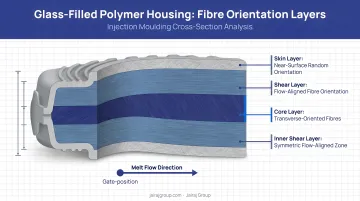
Glass fibre loading complicates this further. Injection moulding creates fibre orientation gradients through the wall thickness, meaning signal attenuation becomes geometry- and orientation-dependent. Engineers should validate RF performance on actual moulded housing samples at the intended fibre loading — not on raw material datasheets.
Dimensional Stability and CTE Mismatch
TPMS housings contain metallic components: brass valve stems, aluminium rim brackets, steel fasteners. The coefficient of thermal expansion (CTE) of engineering plastics is typically 5–10× higher than these metals. Over repeated thermal cycles from –40°C to +125°C, this mismatch generates stress concentrations at the interfaces that can crack the housing, fracture seals, or loosen clamped assemblies.
LCP's anisotropic CLTE offers a meaningful advantage in geometries where directional expansion control matters. Glass fibre reinforcement similarly reduces the bulk CTE of the plastic housing toward metal-compatible values — a direct benefit for interface integrity.
Chemical Compatibility and Total Cost of Ownership
Published chemical resistance charts cover individual reagents at standard conditions. Real service exposes housings to mixtures at elevated temperature — tyre sealant residue plus moisture plus heat behaves differently than any single reagent. Qualification testing should include immersion in actual or simulated service fluids at the upper end of the service temperature range.
Frame material cost as cost-per-good-part, not price-per-kilogram. PPS carries a higher raw material cost than PA66, but total economics depend on several process-level factors:
- Higher mould temperatures required for PPS crystallisation
- Annealing requirements for certain PA grades
- Increased tooling wear from glass-filled compounds
- Scrap rates and secondary operations across the production run
In the right process environment, PPS can deliver lower all-in costs despite a higher starting price.
TPMS housings also need to satisfy REACH and RoHS compliance, and in many cases OEM-specific material approval lists. PPS grades are generally compliant. Some PA formulations using legacy flame-retardant additives may require verification against current SVHC lists. Confirm the regulatory position for the specific grade and additive package — not the material family in general.
Glass Fibre Reinforcement: Structural Gains and Signal Trade-offs
Glass fibre reinforcement addresses several key housing requirements:
- Improved stiffness: maintains housing geometry under centrifugal loading
- Reduced CTE: moves the housing closer to metal component expansion rates
- Better creep resistance: sustains snap-fit and clamped assembly loads over time
Typical TPMS housing specifications use 15–30% glass fibre loading, balancing stiffness gains against processing and signal considerations. Some PPS grades specify 40% GF where maximum rigidity is required.
Glass fibre raises both Dk and Df relative to the base resin, introducing a direction-dependent signal trade-off. Because injection moulding creates non-uniform fibre orientation through the wall cross-section, signal attenuation varies with the angle of transmission relative to the predominant fibre direction.
This anisotropy cannot be captured in a bulk datasheet value. It can only be characterised on actual moulded parts — making part-level RF testing an essential step in housing validation.
Surface finish is a secondary concern. Glass fibre emergence reduces surface smoothness, which can compromise sealing surface quality at the housing-to-valve-stem interface. O-ring and gasket groove surfaces in glass-filled housings should be designed with adequate draft angles, and the tool specification should include polished cavity steel at these surfaces to achieve the required contact geometry.
From Material to Part: Manufacturing and Precision Moulding Considerations
Material selection and process design are not sequential decisions. They must happen in parallel, because the housing geometry constrains which materials are viable before any property comparison begins.
Geometry-Driven Constraints
TPMS housings typically feature:
- Wall thicknesses of 1.2–2.0 mm
- Integrated snap-fit retention features
- Internal ribs and boss structures
- Tight-tolerance bore dimensions for sensor PCB and battery fitment
At these wall thicknesses, melt flow index, gate location, and fill time become as important as tensile strength. A material that performs excellently in a test bar may flow poorly through a 1.2 mm wall with a long flow path, resulting in incomplete fill, weld lines at structurally critical locations, or excessive residual stress.
Shrinkage anisotropy — the difference in shrinkage between the flow direction and the cross-flow direction — is particularly significant for glass-filled semi-crystalline materials. This directly determines whether a housing will hold its bore tolerances after ejection and post-mould cooling.
Managing Warpage in Semi-Crystalline Materials
PPS and glass-filled PA grades are both prone to warpage from differential cooling across uneven wall sections. Warpage is an inevitable consequence of crystallisation kinetics combined with non-uniform geometry. Managing it requires:
- Precise mould temperature control (PPS requires elevated mould temperatures to achieve adequate crystallinity)
- Gate location chosen to balance flow length and minimise weld line placement
- Post-mould annealing for PA grades, which relieves residual stress and stabilises dimensions
- Mould flow simulation before tool cuts to predict and correct differential shrinkage
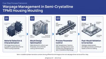
These are process decisions that must be made collaboratively between the material supplier, mould designer, and moulder. Leaving them until after the tool is built is expensive.
The Manufacturing Partner Consideration
TPMS housing quality depends as much on manufacturing capability as material specification. Consistent wall thickness, snap-fit dimensional repeatability, and sealing surface quality require shot-to-shot process stability across production volumes — not just capability demonstrated on a prototype.
Jairaj Group brings 42 years of precision injection moulding experience across automotive-critical components, including PA66-GF sensor housing applications certified under ISO 9001:2015. For OEMs and Tier 1 suppliers evaluating manufacturing partners, the company's in-house tool room, PLC-controlled process monitoring, and Design for Manufacturability collaboration model — covering flow analysis, cooling optimisation, and warpage prediction — support the iterative development that complex housing geometries demand.
Frequently Asked Questions
What plastic material is most commonly used for TPMS sensor housings?
PA66 and PPS are the most widely specified materials. PA66 dominates cost-sensitive mainstream applications due to its processability and established supply base, while PPS is preferred where chemical resistance, near-zero moisture absorption, and higher thermal performance are the primary requirements.
How does moisture absorption in nylon affect TPMS housing performance?
Hygroscopic nylons like PA66 absorb moisture from the tyre environment, causing dimensional swell of up to 1.9% at equilibrium conditions. This affects sensor fit tolerances, sealing surface geometry, and the mechanical properties of the housing itself. PA12 or PPS are specified when dimensional stability under humidity is a design constraint.
Does glass fibre reinforcement in TPMS housings affect RF signal performance?
Yes. Glass fibre raises the dielectric constant and loss tangent of the base resin, attenuating the 315 MHz or 433 MHz TPMS signal in ways that vary by fibre orientation through the moulded wall. RF performance must always be validated on production moulded parts at the actual fibre loading — published datasheet values do not capture this.
What temperature range must a TPMS plastic housing withstand?
The standard automotive range is –40°C to approximately 125°C continuous, with higher peak excursions depending on wheel position and duty cycle. EV platforms are pushing this envelope further, driven by heavier vehicle masses and battery thermal system proximity.
What is the difference between PPS and PA66 for TPMS sensor housing applications?
PPS offers superior chemical resistance, near-zero moisture absorption, and a higher heat deflection temperature than PA66, but at significantly higher material cost and with more demanding process requirements. PA66 offers lower cost and easier processability. PPS is the higher-performing choice; PA66 remains viable where its hygroscopicity can be managed through design.
Are the same plastic grades used for both direct-mount and valve-stem TPMS sensors?
The same material families apply to both, but direct-mount and valve-stem sensors differ in geometric constraints and chemical exposure — differences significant enough to shift the optimal grade. Always base material selection on the specific housing geometry and operating environment, not the sensor type alone.